 |
SyterKit 0.4.0.x
SyterKit is a bare-metal framework
|
Loading...
Searching...
No Matches
|
SyterKit 0.4.0.x
SyterKit is a bare-metal framework
|
#include <io.h>#include <stdarg.h>#include <stdbool.h>#include <stddef.h>#include <stdint.h>#include <types.h>#include <log.h>#include <mmu.h>#include <sys-clk.h>#include <sys-dram.h>#include <common.h>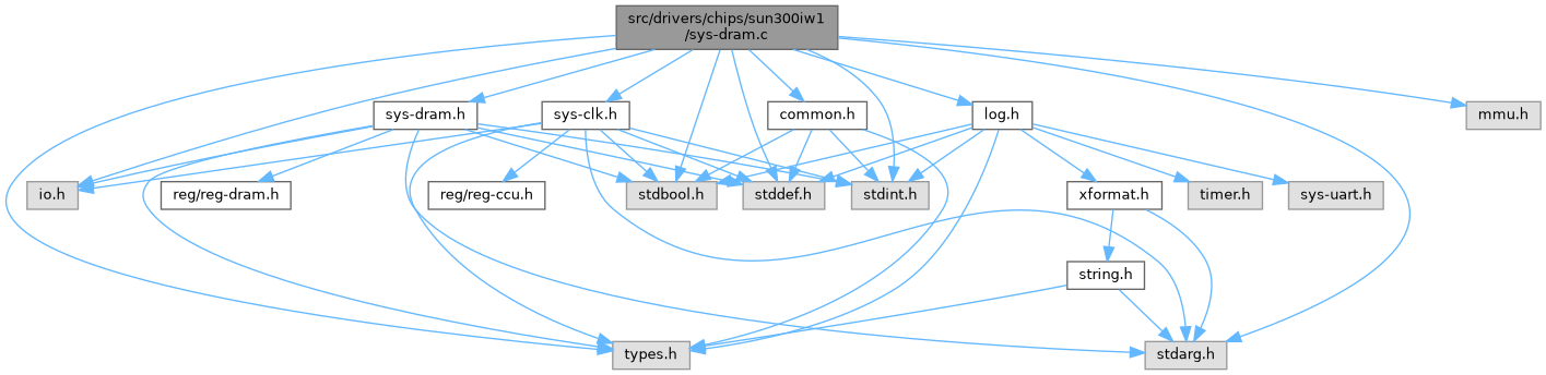
Macros | |
| #define | DIV_ROUND_UP(a, b) (((a) + (b) -1) / (b)) |
| #define | CONFIG_SYS_SDRAM_BASE SDRAM_BASE |
Functions | |
| static int | ns_to_t (dram_para_t *para, int nanoseconds) |
| Convert nanoseconds to clock cycles for DRAM timing. | |
| static void | dram_enable_all_master (void) |
| Enable all DRAM masters. | |
| static void | dram_disable_all_master (void) |
| Disable all DRAM masters. | |
| static void | eye_delay_compensation (dram_para_t *para) |
| Perform eye delay compensation for DRAM timings. | |
| static void | mctl_set_timing_params (dram_para_t *para) |
| Set the DRAM timing parameters for the specified DRAM type. | |
| static int | ccu_set_pll_ddr_clk (int index, dram_para_t *para) |
| Set the DDR PLL clock based on the given DRAM parameters. | |
| static void | mctl_sys_init (dram_para_t *para) |
| Initializes the MCTL (Memory Controller) system by configuring the DRAM and MBUS clocks and resets. | |
| static void | mctl_com_init (dram_para_t *para) |
| Initializes the memory controller with the specified parameters. | |
| static unsigned int | mctl_channel_init (unsigned int ch_index, dram_para_t *para) |
| Initializes the memory controller channel with the provided DRAM parameters. | |
| static unsigned int | calculate_rank_size (uint32_t regval) |
| Calculates the size of a memory rank based on the provided register value. | |
| static unsigned int | get_dram_size (void) |
| Retrieves the total size of the DRAM. | |
| static int | dqs_gate_detect (dram_para_t *para) |
| Detects the DQS gate state and updates DRAM parameters based on the detected configuration. | |
| static int | dramc_simple_wr_test (unsigned int mem_mb, int len) |
| Performs a simple write-read test on the DRAM to verify its functionality. | |
| static void | mctl_vrefzq_init (dram_para_t *para) |
| Initializes the Vref mode for the memory controller. | |
| static int | mctl_core_init (dram_para_t *para) |
| Initializes the memory controller. | |
| static int | auto_scan_dram_size (dram_para_t *para) |
| Scans and sizes a DRAM device by cycling through address lines to determine the configuration. | |
| static int | auto_scan_dram_rank_width (dram_para_t *para) |
| Automatically scans and detects DRAM rank and DQ width. | |
| static int | auto_scan_dram_config (dram_para_t *para) |
| Automatically scans and configures the SDRAM topology. | |
| static int | init_DRAM (int type, dram_para_t *para) |
| Initializes the DRAM controller and configures memory parameters. | |
| uint32_t | sunxi_dram_init (void *para) |
| Initializes the DRAM with the given parameters. | |
| #define CONFIG_SYS_SDRAM_BASE SDRAM_BASE |
| #define DIV_ROUND_UP | ( | a, | |
| b | |||
| ) | (((a) + (b) -1) / (b)) |
|
static |
Automatically scans and configures the SDRAM topology.
This function determines the SDRAM topology by performing a series of scans. First, it scans and establishes the number of ranks and the DQ width. Then, it scans the SDRAM address lines to determine the size of each rank. After the scan, it updates the dram_tpr13 register to reflect that the SDRAM topology has been successfully detected. The updated value of dram_tpr13 ensures that the auto-scan is not repeated upon a re-initialization.
The function follows these steps:
dram_tpr13 register does not indicate that the number of ranks and DQ width have been determined (bit 14 not set), it calls auto_scan_dram_rank_width() to perform the scan. If the scan fails, it logs an error message and returns 0.dram_tpr13 register does not indicate that the size of each rank is known (bit 0 not set), it calls auto_scan_dram_size() to determine the size of each rank. If the scan fails, it logs an error message and returns 0.dram_tpr13 is not set, it sets the appropriate bits in dram_tpr13 to indicate that the SDRAM topology is now known.| para | Pointer to the dram_para_t structure that holds the SDRAM parameters. |
1 if the SDRAM configuration was successfully determined, or 0 if an error occurred during the scan.auto_scan_dram_rank_width() and auto_scan_dram_size() are properly implemented and return 0 on failure and non-zero on success.
|
static |
Automatically scans and detects DRAM rank and DQ width.
This function configures the DRAM controller to test for the number of ranks (1 or 2) and the DQ width (full or half). It sets up the parameters with dqs_gating_mode equal to 1 and enables two ranks. It then configures the controller and performs tests to detect the rank and width. The function also resets the parameters to their original values after the scan.
The steps performed by this function are as follows:
dram_tpr13 and dram_para1 in local variables.dram_tpr13 register.mctl_core_init() to initialize the memory controller with the new configuration.PGSR0) is set, indicating an error.dqs_gate_detect() to detect the DRAM DQS gating status.0 to indicate the scan was unsuccessful.dram_tpr13 and dram_para1.1 to indicate the scan was successful.| para | Pointer to the dram_para_t structure that holds the DRAM parameters to be tested. |
1 if the rank and width detection was successful, or 0 if it failed.mctl_core_init() and dqs_gate_detect() are properly implemented. It also assumes that the DRAM controller and PHY registers are accessible and can be modified as needed.
|
static |
Scans and sizes a DRAM device by cycling through address lines to determine the configuration.
This function performs an auto-scan of the DRAM to determine its size by cycling through various address lines and checking if they correspond to real memory addresses or mirrored addresses. The process involves adjusting and testing column, row, and bank bit allocations, and determining the number of address lines for each part. The results are then stored in the dram_para1 and dram_para2 parameters.
The procedure follows these steps:
mctl_core_init().The results for row size, bank size, and page size are stored in the dram_para1 structure, while the dual rank configuration is updated in dram_para2.
| para | Pointer to a dram_para_t structure that holds the configuration and result of the DRAM scan. |
| 0 | If the DRAM initialization failed. |
CONFIG_SYS_SDRAM_BASE. It uses hardware-specific register operations to configure and test the DRAM controller.
|
static |
Calculates the size of a memory rank based on the provided register value.
This function computes the size of a memory rank using the information embedded in the given register value. The register value is interpreted as follows:
The calculation subtracts 14 (representing 1MB = 20 bits, minus an additional 6 bits), and then returns the size of the memory rank as a power of 2.
| regval | The register value containing memory configuration information. The value is assumed to be formatted with page size, row width, and bank count information located in specific bit ranges:
|
|
static |
Set the DDR PLL clock based on the given DRAM parameters.
This function configures the PLL clock for the DDR memory controller based on the DRAM parameters passed in the dram_para_t structure. It calculates the PLL parameters (such as the PLL multiplier and divider) and writes them to the appropriate registers to enable the PLL and ensure it locks to the desired frequency. It also configures the DRAM clock source to use the PLL.
The PLL is configured using the following parameters:
The function uses hardware registers to configure the PLL and waits for the PLL to lock before enabling the output gate and selecting the PLL as the clock source for the DRAM controller.
| index | The index used to determine which PLL clock configuration to use. This is typically used to select different PLL configurations based on the input parameters. |
| para | A pointer to a structure containing the DRAM parameters, including:
|
hosc_freq). The function assumes that dram_tpr13, dram_tpr9, and dram_tpr10 contain the necessary information for PLL configuration.dram_para_t structure are valid and appropriate for your system configuration before calling this function.
|
static |
Detects the DQS gate state and updates DRAM parameters based on the detected configuration.
This function performs a series of hardware register reads to detect the state of the DQS (Data Strobe) gate in a DRAM system. It checks the configuration of the DRAM system and modifies the dram_para2 field of the dram_para_t structure to reflect the detected DRAM parameters, such as rank and DQ (Data Queue) configuration. Based on the detection, the function will set the appropriate flags for dual rank, single rank, full DQ, or half DQ memory configurations.
The function reads values from specific registers:
MCTL_PHY_PGSR0 to check if the DRAM is dual rank.MCTL_PHY_DXnGSR0(0) and MCTL_PHY_DXnGSR0(1) to check the state of the DQS gate and determine the DQ configuration.The detected configuration is then used to update para->dram_para2, and appropriate debug messages are logged.
| para | Pointer to the dram_para_t structure which holds DRAM configuration parameters. |
MCTL_PHY_BASE, MCTL_PHY_PGSR0, etc.) are correctly mapped and accessible in the memory space. It also relies on the presence of specific debug logging mechanisms (printk_debug).
|
static |
Disable all DRAM masters.
This function disables all masters in the DRAM controller by writing to the appropriate registers. It also introduces a small delay to ensure the changes are applied.
|
static |
Enable all DRAM masters.
This function enables all masters in the DRAM controller by writing to the appropriate registers. It also introduces a small delay to ensure the changes are applied.
|
static |
Performs a simple write-read test on the DRAM to verify its functionality.
This function writes two distinct patterns to different memory regions in the DRAM and then reads back the written values to check for consistency. The test is performed on half of the specified memory size, with pattern patt1 written to the first half and pattern patt2 written to the second half. The function verifies that the read values match the expected patterns at the corresponding addresses. If any mismatch is found, the function logs an error and returns a failure code.
The function works as follows:
mem_mb), and uses this offset to write to the second half of the memory.patt1 and patt2 to the first and second halves of the memory, respectively.patt1 and patt2).1 indicating failure.0 indicating success.| mem_mb | Total size of the DRAM in megabytes. |
| len | Number of memory locations (in words) to test. |
CONFIG_SYS_SDRAM_BASE and that the system supports 32-bit word writes and reads. The function also assumes that the memory is properly initialized.
|
static |
Perform eye delay compensation for DRAM timings.
This function configures various delay parameters for DRAM by manipulating specific PHY (Physical Layer) control registers. The compensation ensures that the timing of various signal transitions (e.g., DQS, RAS, CAS) is optimized for the DRAM device, based on the provided timing parameters. The adjustments are based on values extracted from the dram_para_t structure. The function configures the appropriate delay settings for data signals, command signals, and other necessary PHY control registers.
| para | Pointer to a structure containing the DRAM timing parameters. These parameters are used to configure delays for various signal lines in the DRAM controller. |
|
static |
Retrieves the total size of the DRAM.
This function calculates the total size of the DRAM by reading memory configuration values from two registers (MCTL_COM_WORK_MODE0 and MCTL_COM_WORK_MODE1) and interpreting the memory rank configurations. It determines whether the system has a single rank, two identical ranks, or two distinct ranks based on the values read from the registers.
The function uses the calculate_rank_size() helper function to determine the size of individual ranks.
MCTL_COM_BASE + MCTL_COM_WORK_MODE0, MCTL_COM_BASE + MCTL_COM_WORK_MODE1) are correctly mapped and accessible in the memory space.
|
static |
Initializes the DRAM controller and configures memory parameters.
This function initializes the DRAM controller and configures various settings based on the provided dram_para_t structure. It configures the DRAM clock, type, ZQ calibration, SDRAM size, hardware auto-refresh, ODT (On Die Termination) settings, and more. The function also ensures that the DRAM controller is properly initialized for the specified memory type (DDR2, DDR3, LPDDR2, LPDDR3, etc.).
The following steps are performed:
auto_scan_dram_config to scan and configure the DRAM topology.mctl_core_init.dram_para2 parameter.| type | The type of DRAM to initialize (not used in the function body, but typically used to specify DDR2, DDR3, LPDDR2, etc.). |
| para | Pointer to a dram_para_t structure containing DRAM configuration parameters, such as clock, type, ODT settings, and other controller parameters. |
|
static |
Initializes the memory controller channel with the provided DRAM parameters.
This function configures the memory controller channel based on the provided DRAM parameters. It sets the DDR clock, adjusts PHY registers for DQS gating mode, enables/disable ODT (On-Die Termination), configures PLL and SSCG, applies timing and voltage parameters, and performs necessary DRAM controller initialization and calibration steps. The function also handles power gating and waits for the status signals to complete.
| ch_index | The index of the memory channel to initialize (not used in this implementation). |
| para | Pointer to a structure containing the DRAM configuration parameters. This structure includes:
|
|
static |
Initializes the memory controller with the specified parameters.
This function configures the memory controller by setting various parameters such as SDRAM type, word width, rank, bank, row, and address mapping. It also configures additional settings like the controller wait time, ODTMAP, and specific register values for different DRAM configurations.
| para | Pointer to a structure containing the DRAM parameters. The structure should contain values such as DRAM type, size, ranks, timing parameters, and other relevant settings. |
|
static |
Initializes the memory controller.
This function performs a three-stage initialization of the memory controller:
The function performs the following operations in sequence:
mctl_sys_init() to initialize the system parameters.mctl_vrefzq_init() to configure the voltage reference settings.mctl_com_init() to initialize the memory controller communication settings.mctl_set_timing_params() to set the timing parameters for the memory controller.mctl_channel_init() to initialize the memory channel with the given parameters.| para | Pointer to the dram_para_t structure that holds the memory controller's configuration parameters. |
0 typically indicates success.mctl_sys_init(), mctl_vrefzq_init(), mctl_com_init(), mctl_set_timing_params(), and mctl_channel_init() functions are correctly implemented and that they are responsible for various aspects of memory controller configuration.
|
static |
Set the DRAM timing parameters for the specified DRAM type.
This function configures various timing parameters for the DRAM controller based on the DRAM type and clock speed specified in the dram_para_t structure. It sets the timing values for the DRAM and writes them to the appropriate registers. The function supports multiple DRAM types, including DDR2, DDR3, LPDDR2, and LPDDR3.
The following parameters are configured:
| para | Pointer to a structure that contains the DRAM parameters, including:
|
ns_to_t helper function to convert nanosecond values to clock cycles based on the DRAM clock frequency. The DRAM type and clock speed influence the specific values of the timing parameters.
|
static |
Initializes the MCTL (Memory Controller) system by configuring the DRAM and MBUS clocks and resets.
This function initializes the Memory Controller by performing a sequence of hardware register writes to assert and deassert resets, configure clock gating, and enable the necessary clock sources for DRAM operation. It configures the DRAM clock PLL and updates the clock settings based on the system's oscillator frequency (HOSC). Additionally, it enables the MCTL clock and prepares the system for further memory operations.
The steps performed by this function include:
This function directly manipulates hardware registers for clock configuration, reset control, and memory initialization. It's intended for low-level hardware initialization and should be executed early in the system's startup sequence.
| para | A pointer to a structure of type dram_para_t which contains the DRAM configuration parameters, including the DRAM clock frequency and PLL settings. |
udelay to introduce delays, which might not be precise on all platforms. Ensure that the delays are sufficient for your platform's clock configuration to take effect.dram_tpr10 register in para is modified to configure the HOSC frequency based on whether the system is using a 40 MHz or a different oscillator frequency.ccu_set_pll_ddr_clk function is called to configure the PLL for DRAM based on the passed parameters. It returns the actual DRAM frequency, which is stored in para->dram_clk.
|
static |
Initializes the Vref mode for the memory controller.
This function configures the voltage reference (Vref) settings for the memory controller by modifying the appropriate registers. It uses the dram_para_t structure to determine the settings based on the provided configuration parameters.
The function performs the following steps:
dram_tpr13 is set (bit 17). If it is, the function returns early and does nothing.MCTL_PHY_IOVCR0 register to set the appropriate I/O voltage reference values based on the dram_tpr5 configuration. Only the lower 32 bits of dram_tpr5 are used for this purpose.dram_tpr13 is not set, it modifies the MCTL_PHY_IOVCR1 register to adjust another set of voltage reference settings based on the lower 7 bits of dram_tpr6.The function utilizes the clrsetbits_le32 helper to modify specific bits of the I/O voltage reference control registers without affecting the other bits.
| para | Pointer to the dram_para_t structure containing the configuration parameters. |
MCTL_PHY_BASE) and the corresponding register offsets (MCTL_PHY_IOVCR0 and MCTL_PHY_IOVCR1) are defined elsewhere in the code. Additionally, the function assumes that the dram_para_t structure contains valid values for the voltage reference configuration.
|
static |
Convert nanoseconds to clock cycles for DRAM timing.
This function calculates the corresponding number of clock cycles for a given duration in nanoseconds, based on the DRAM controller clock frequency.
| para | Pointer to a struct containing DRAM parameters, including the clock frequency. |
| nanoseconds | The time duration in nanoseconds to be converted. |
| uint32_t sunxi_dram_init | ( | void * | para | ) |
Initializes the DRAM with the given parameters.
Initialize the DRAM.
This function initializes the DRAM using the provided parameters encapsulated in the dram_para_t structure. It calls the init_DRAM function to perform the actual initialization and returns the result.
| para | A pointer to the dram_para_t structure that contains DRAM initialization parameters. The function casts this void pointer to a dram_para_t pointer. |
init_DRAM function call, which represents the size of the initialized DRAM in MB. A return value of 0 indicates failure.